Guides › Circuit to connect and logic gates
Circuit to connect and logic gates
Published October 16, 2026.
Two mechanisms play with current. In one you draw the path; in the other you set switches so that logic gates let the current through. In both, validation goes through a lever, which is an attempt.
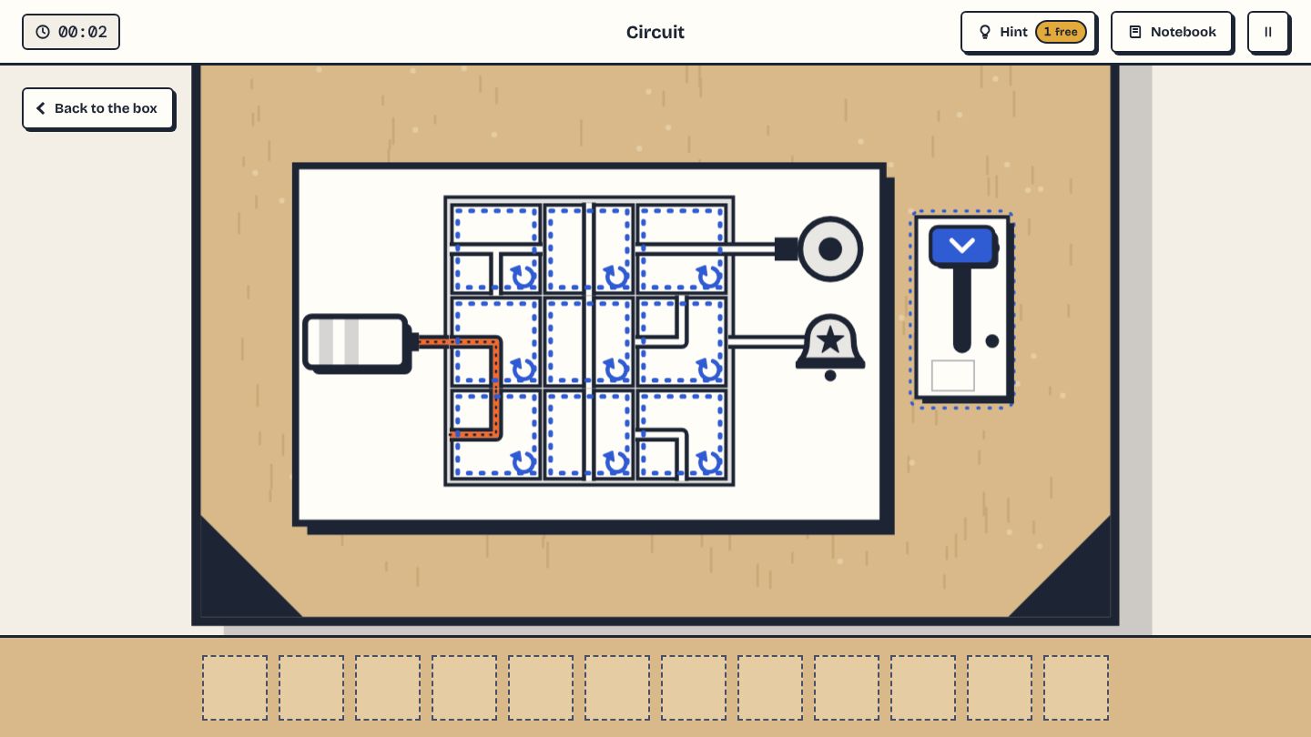
Circuit to connect: a single right path
Tap a tile to turn it a quarter turn. The current leaves the battery and spreads live: you see at once what it reaches. It must arrive at the receiver carrying the symbol shown on the badge, without lighting the others, then you pull the lever. Receivers are bulbs or bells, each with its symbol.
There is only one path to the right receiver, and there are decoys: at least one other receiver, and a decoy path that you must remember to cut so as not to light it. Tiles that are not on the right path can be oriented as you like.
A method for the circuit
Start from the end: find the wanted receiver and work back towards the battery, looking at which tiles can lead to it. Place the tiles of the path, then only afterwards the tiles that could let current leak to a decoy. A lever pulled with a wrong circuit costs 15 seconds: check by eye first.
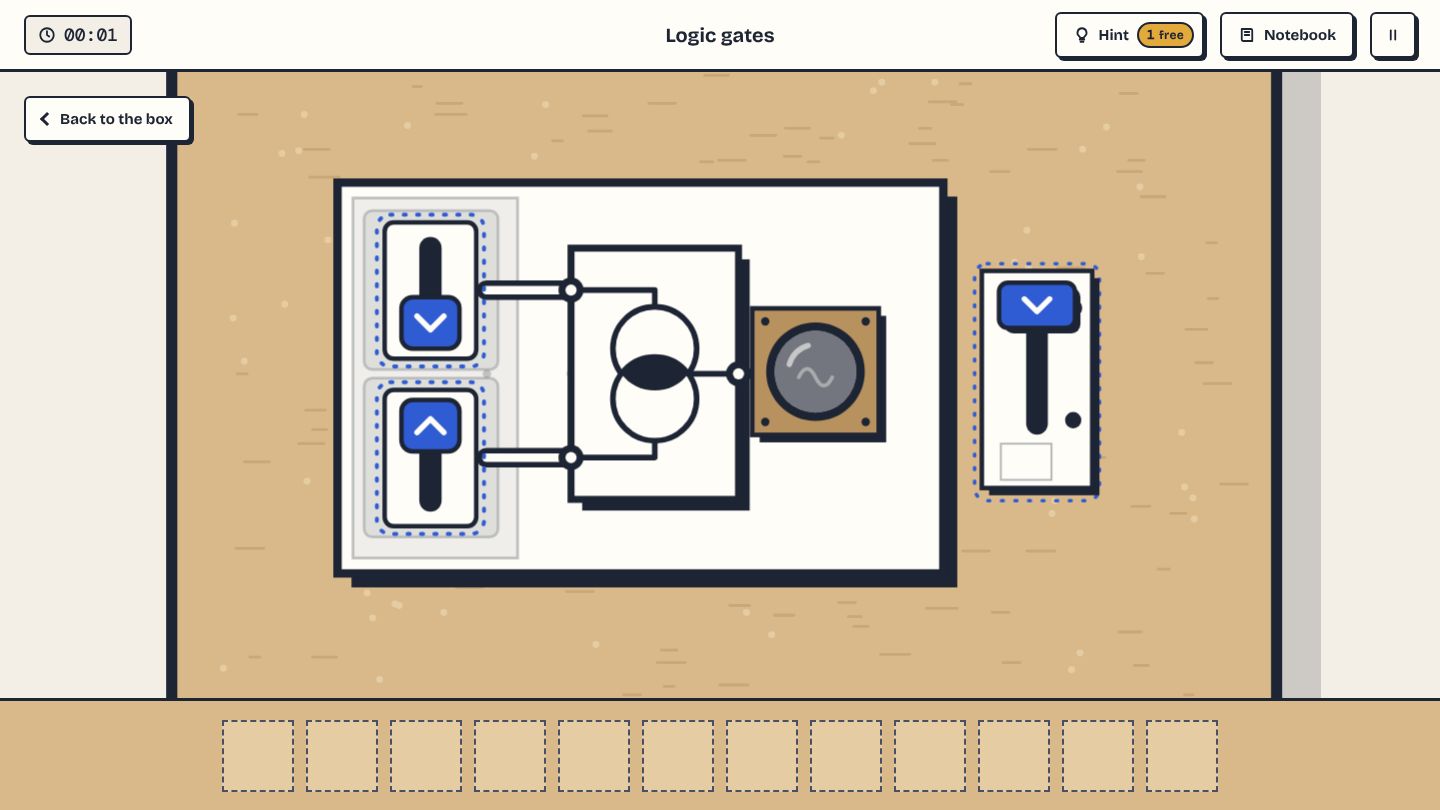
Logic gates: current only exists during the test
Switches go up or down. Then pull the test lever: current only flows during the test, and the lamp only lights if the gates let it through. The lamp is never on at rest: if it were, the AND and OR gates would be solved from the start.
The gate plate explains what each one does, with an example sentence.
AND, OR, NOT: a reminder
An AND gate only lets current through if both its inputs are active. An OR gate lets it through if at least one input is active. A NOT gate inverts: it lets current through when its input is cut. For a large frame, work from the lamp towards the switches: what does the lamp depend on? Then, which inputs of that gate must be activated?
Practise in the game
The game's tutorials, with no clock and no penalty, let you practise this subject: